- 您现在的位置:买卖IC网 > Sheet目录3876 > PIC18F4331T-I/ML (Microchip Technology)IC MCU FLASH 4KX16 44QFN
2010 Microchip Technology Inc.
DS39616D-page 25
PIC18F2331/2431/4331/4431
2.0
GUIDELINES FOR GETTING
STARTED WITH PIC18F
MICROCONTROLLERS
2.1
Basic Connection Requirements
Getting started with the PIC18F2331/2431/4331/4431
family of 8-bit microcontrollers requires attention to a
minimal set of device pin connections before
proceeding with development.
The following pins must always be connected:
All VDD and VSS pins
All AVDD and AVSS pins, regardless of whether or
not the analog device features are used
MCLR pin
These pins must also be connected if they are being
used in the end application:
PGC/PGD pins used for In-Circuit Serial
Programming (ICSP) and debugging purposes
(see Section 2.4 “ICSP Pins”)
OSCI and OSCO pins when an external oscillator
source is used
Additionally, the following pins may be required:
VREF+/VREF- pins are used when external voltage
reference for analog modules is implemented
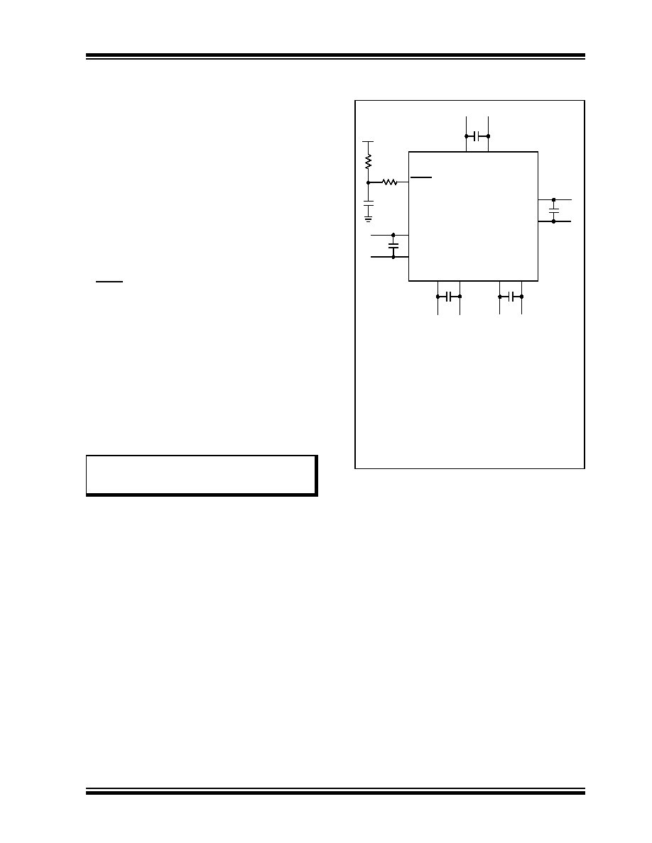
The minimum mandatory connections are shown in
FIGURE 2-1:
RECOMMENDED
MINIMUM CONNECTIONS
Note:
The AVDD and AVSS pins must always be
connected, regardless of whether any of
the analog modules are being used.
PIC18FXXXX
V
DD
V
SS
VDD
VSS
VDD
AV
DD
AV
SS
V
DD
V
SS
C1
R1
VDD
MCLR
R2
C2(1)
C3(1)
C4(1)
C5(1)
C6(1)
Key (all values are recommendations):
C1 through C6: 0.1 F, 20V ceramic
R1: 10 k
R2: 100 to 470
Note
1:
The example shown is for a PIC18F device
with five VDD/VSS and AVDD/AVSS pairs.
Other devices may have more or less pairs;
adjust the number of decoupling capacitors
appropriately.
发布紧急采购,3分钟左右您将得到回复。
相关PDF资料
PIC16F690-I/ML
IC PIC MCU FLASH 4KX14 20QFN
PIC16C56A-04I/P
IC MCU OTP 1KX12 18DIP
PIC18F45J10-I/PT
IC PIC MCU FLASH 16KX16 44TQFP
PIC24F16KA101-I/SS
IC PIC MCU FLASH 16K 20-SSOP
PIC18LF14K50-I/SS
IC PIC MCU FLASH 16K 1.8V 20SSOP
PIC18F14K50-I/SS
IC PIC MCU FLASH 8KX16 20-SSOP
PIC24F08KL302-I/ML
IC MCU 16BIT 8KB FLASH 28-QFN
PIC24F08KL302-I/MQ
IC MCU 16BIT 8KB FLASH 28-QFN
相关代理商/技术参数
PIC18F4331T-I/PT
功能描述:8位微控制器 -MCU 8KB 768 RAM 34 I/O RoHS:否 制造商:Silicon Labs 核心:8051 处理器系列:C8051F39x 数据总线宽度:8 bit 最大时钟频率:50 MHz 程序存储器大小:16 KB 数据 RAM 大小:1 KB 片上 ADC:Yes 工作电源电压:1.8 V to 3.6 V 工作温度范围:- 40 C to + 105 C 封装 / 箱体:QFN-20 安装风格:SMD/SMT
PIC18F43K20-E/ML
功能描述:8位微控制器 -MCU 8 KB Enh Flash 768 RAM 36 I/O Pb Free RoHS:否 制造商:Silicon Labs 核心:8051 处理器系列:C8051F39x 数据总线宽度:8 bit 最大时钟频率:50 MHz 程序存储器大小:16 KB 数据 RAM 大小:1 KB 片上 ADC:Yes 工作电源电压:1.8 V to 3.6 V 工作温度范围:- 40 C to + 105 C 封装 / 箱体:QFN-20 安装风格:SMD/SMT
PIC18F43K20-E/MV
功能描述:8位微控制器 -MCU 8KB FL 768b RAM 8bit Familynanowatt XLP
RoHS:否 制造商:Silicon Labs 核心:8051 处理器系列:C8051F39x 数据总线宽度:8 bit 最大时钟频率:50 MHz 程序存储器大小:16 KB 数据 RAM 大小:1 KB 片上 ADC:Yes 工作电源电压:1.8 V to 3.6 V 工作温度范围:- 40 C to + 105 C 封装 / 箱体:QFN-20 安装风格:SMD/SMT
PIC18F43K20-E/P
功能描述:8位微控制器 -MCU 8 KB Enh Flash 768 RAM 36 I/O Pb Free RoHS:否 制造商:Silicon Labs 核心:8051 处理器系列:C8051F39x 数据总线宽度:8 bit 最大时钟频率:50 MHz 程序存储器大小:16 KB 数据 RAM 大小:1 KB 片上 ADC:Yes 工作电源电压:1.8 V to 3.6 V 工作温度范围:- 40 C to + 105 C 封装 / 箱体:QFN-20 安装风格:SMD/SMT
PIC18F43K20-E/PT
功能描述:8位微控制器 -MCU 8 KB Enh Flash 768 RAM 36 I/O Pb Free RoHS:否 制造商:Silicon Labs 核心:8051 处理器系列:C8051F39x 数据总线宽度:8 bit 最大时钟频率:50 MHz 程序存储器大小:16 KB 数据 RAM 大小:1 KB 片上 ADC:Yes 工作电源电压:1.8 V to 3.6 V 工作温度范围:- 40 C to + 105 C 封装 / 箱体:QFN-20 安装风格:SMD/SMT
PIC18F43K20-I/ML
功能描述:8位微控制器 -MCU 8 KB Enh Flash 768 RAM 36 I/O Pb Free RoHS:否 制造商:Silicon Labs 核心:8051 处理器系列:C8051F39x 数据总线宽度:8 bit 最大时钟频率:50 MHz 程序存储器大小:16 KB 数据 RAM 大小:1 KB 片上 ADC:Yes 工作电源电压:1.8 V to 3.6 V 工作温度范围:- 40 C to + 105 C 封装 / 箱体:QFN-20 安装风格:SMD/SMT
PIC18F43K20-I/MV
功能描述:8位微控制器 -MCU 8KB FL 768b RAM 8bit Familynanowatt XLP
RoHS:否 制造商:Silicon Labs 核心:8051 处理器系列:C8051F39x 数据总线宽度:8 bit 最大时钟频率:50 MHz 程序存储器大小:16 KB 数据 RAM 大小:1 KB 片上 ADC:Yes 工作电源电压:1.8 V to 3.6 V 工作温度范围:- 40 C to + 105 C 封装 / 箱体:QFN-20 安装风格:SMD/SMT
PIC18F43K20-I/P
功能描述:8位微控制器 -MCU 8 KB Enh Flash 768 RAM 36 I/O Pb Free RoHS:否 制造商:Silicon Labs 核心:8051 处理器系列:C8051F39x 数据总线宽度:8 bit 最大时钟频率:50 MHz 程序存储器大小:16 KB 数据 RAM 大小:1 KB 片上 ADC:Yes 工作电源电压:1.8 V to 3.6 V 工作温度范围:- 40 C to + 105 C 封装 / 箱体:QFN-20 安装风格:SMD/SMT